PWM and Triangular Wave Generators | Create Precise Waveforms with PWM and Triangular Techniques
You may be already aware of the PWM and triangular wave generator.
There are different kinds of waves such as sine waves, square waves, and triangle waves. Triangle waves are commonly found and used in audio production, and they are a common waveform source on synthesizers.
On the other hand, pulse width modulation (PWM) is a method of changing the duration of a pulse with respect to any analog input. The duty cycle of a square wave is modulated to encode a specific analog signal level.
Both PWM and triangular waves have significant applications in different electronic projects. In this article, we are going to demonstrate 4 different wave generator circuits using some simple components. Here are the projects that you’ll get to learn from below –
- PWM generator circuit using 741 op-amp comparator with output waveform.
- The PWM in MATLAB using simple MATLAB functions.
- Triangular wave generator using op amp 741 including working schemes and simulated output waveform.
- Simple generating pulse width modulation using pic microcontroller Mikro C & amp, and Proteus simulation.
So, without wasting any time, let’s learn in detail and make your own wave generator circuit for your final year electronic project.
1. PWM Generator Circuit Using 741 Op-Amp Comparator With Output Wave Form
Pulse width modulation (PWM) DC motor control is one of the popular circuits in Robotics. This pulse-width modulation tutorial gives you the basic principle of the generation of PWM signal. These signals are used to approximate time-varying analog signals. PWM is employed in a wide variety of applications, ranging from measurement and communications to power control and conversion. Also, this controller is commonly used for speed-controlling motors, fans, lights in varying intensities, etc. Let’s learn more about this below.
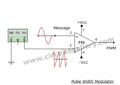
PWM Generator Circuit Diagram
Here is the pulse width modulation generator circuit diagram (pulse width modulator) using op-amp.
PWM Generator Circuit Requirements Using 741 Op-Amp
- Dual power supply (+Vcc and -Vcc)
- 741 op amp IC
- Signal generator
Working of Pulse Width Modulator
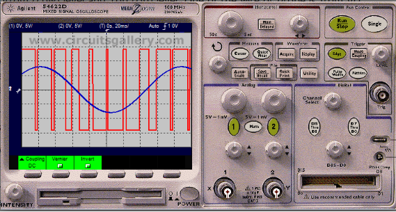
- In this pulse width modulation circuit op amp acts as a comparator.
- It compares both the input voltages- the sawtooth waveform and the message signal (sine wave).
- The duration in which the instantaneous value of sine wave is above that of sawtooth, the op amp switches to +Vcc. It’s because the sine wave input is connected to the non inverting input of the op amp.
- On the contrary, when the value of sine wave is less than the instantaneous value of sawtooth, op amp switches to -Vcc.
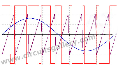
- Thus we get a pulse waveform swinging between +Vcc and –Vcc.
- That is the pulse width changes according to the message signal (Width of the pulse is modulated)
Output Wave Form
Important Terms Associated With Pwm
Period (T)
How long each complete pulse cycle takes
Frequency (F)
How often the pulses are generated. This value is typically specified in Hz (cycles per second).

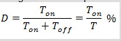
Duty Cycle (D)
Refers to the ratio of time in the period that the pulse is active or high (T on) to the total time of a cycle (T). The duty cycle is typically specified as a percentage of the full period.
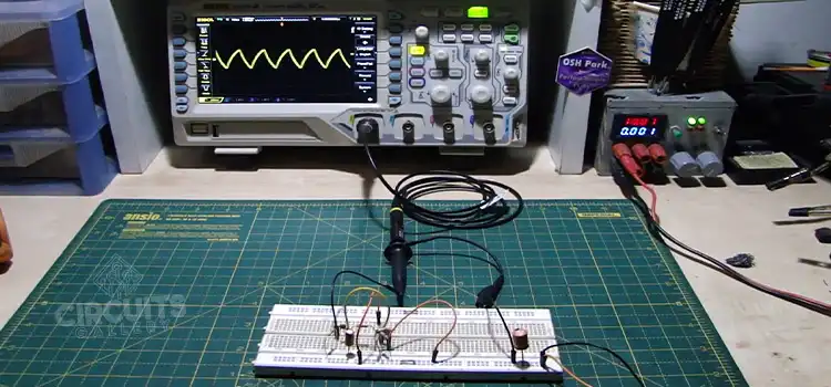
Simulation/Oscilloscope Waveshapes
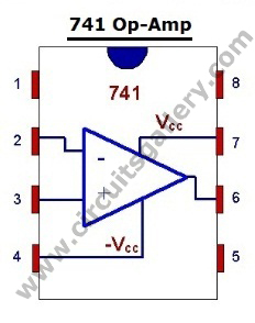
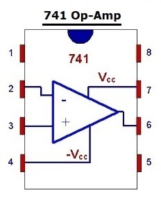
741 pin out
The use of 741 IC in Pulse Width Modulation (PWM) Generator Circuit is so vital and versatile that you may do the modulation according to any sort of message signal you intend to. Besides, by the use of relays of required ratings, you can incorporate unprecedented controls and automation in your projects.
2. Code for PWM (Pulse Width Modulation) Generation in Matlab
We have already discussed the PWM generator circuit using 741 Op-amp in the previous section. Now, let’s check how you can program the PWM in Matlab. In addition to communication systems, PWM is also used in voltage regulators such as Switched Mode Power Supplies (SMPS) to control the power delivered to the load. PWM can be generated using a comparator to which the modulating signal and a reference ramp (sawtooth) waveform are fed.
The code for PWM simulation in MATLAB is shown below.
Note:
- The use of a particular line of MATLAB code is also given as comments (%Comment field).
- The given MATLAB program accepts two input frequencies from the user.
Pwm Matlab Codes
clc;
clear all;
close all;
F2=input(‘Message frequency=’);
F1=input(‘Carrier Sawtooth frequency=’);
A=5;
t=0:0.001:1;
c=A.*sawtooth(2*pi*F1*t);%Carrier sawtooth
subplot(3,1,1);
plot(t,c);
xlabel(‘time’);
ylabel(‘Amplitude’);
title(‘Carrier sawtooth wave’);
grid on;
m=0.75*A.*sin(2*pi*F2*t);%Message amplitude must be less than Sawtooth
subplot(3,1,2);
plot(t,m);
xlabel(‘Time’);
ylabel(‘Amplitude’);
title(‘Message Signal’);
grid on;
n=length(c);%Length of carrier sawtooth is stored to ‘n’
for i=1:n%Comparing Message and Sawtooth amplitudes
if (m(i)>=c(i))
pwm(i)=1;
else
pwm(i)=0;
end
end
subplot(3,1,3);
plot(t,pwm);
xlabel(‘Time’);
ylabel(‘Amplitude’);
title(‘plot of PWM’);
axis([0 1 0 2]);%X-Axis varies from 0 to 1 & Y-Axis from 0 to 2
grid on;
Generated Pwm Signal
Inputs and Observation:
Message frequency=1
Carrier Saw tooth frequency=10
You can use these Matlab codes for simulating any kind of project on Simulink.
3. Triangular Wave Generator Using Op Amp 741 | Working and Simulated Output Waveform
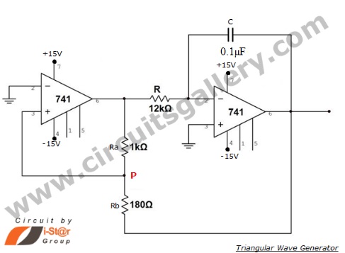
An operational amplifier-based triangular wave generator using op-amp 741 is a simple circuit that is widely used in function generators. To make this circuit you need to understand how a triangular wave transforms. A triangular wave is the output of an integrator if the input to it is a square wave. It means that a triangular wave generator can be formed by simply cascading an integrator and a square wave generator, as illustrated in the figure. We will use two operational amplifiers in this circuit. The first is the op-amp functions as a comparator and the second is the op-amp as an integrator.
Circuit Diagram of Triangular Wave Generator
Components Required for Triangular Wave Generator
- Resistors (1kΩ, 12kΩ, 180Ω)
- Op Amp 741×2
- Capacitor (0.1µF)
Working of Triangular Wave Generator Using Op Amp 741
- At first, the comparator compares the voltage at a point ‘P’ continuously with respect to the voltage at the inverting input. This point is at ground potential.
- As soon as, the voltage at P goes slightly below zero, the output of the comparator will switch to negative saturation.
- Consider the output of the comparator is +Vsat. Since this voltage is the input of the integrator, then its output will be a negative going ramp.
- As a result, one end of the potential divider R1 R2 is at +Vsat and another end is at a negative going ramp. When the negative going ramp attains a value say –Vramp the effective voltage at P becomes slightly less than 0V. This switches the output of the comparator to –Vsat.
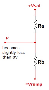
- By this time, integrator output will be a positive going ramp. When the value of the positive going ramp attains +Vramp, the voltage at ‘P’ becomes slightly greater than 0V. There by switching the comparator output to +Vsat.
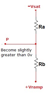
- This cycle repeats and generates a triangular waveform
- A triangular waveform can also be generated by integrating a square wave from an astable multivibrator.
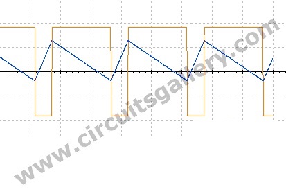
Output Waveform
Design of Triangular Wave Generator
The frequency of the triangular waveform is given by either the following expressions
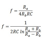
Peak to peak amplitude of ramp voltage is

Components Pin Out of Op Amp 741
Simulated Output Waveform
The output waveform of the triangular wave generator using simulated using Multisim
The simulated output almost matches the theoretical output. Thus, You can easily generate a triangular wave using an operational amplifier following the above tutorial.
4. Simple Generating Pulse Width Modulation Using PIC Microcontroller | Mikro C &Amp | Proteus Simulation
PWM has wide applications in automation such as DC motor speed control circuits, generating analog signals from digital signals, and LED brightness control. In this section, we’ve provided a detailed explanation and simulation of PWM generation using a PIC16F877A microcontroller. We have used Mikro C pro for pic microcontroller programming because it has inbuilt library functions to do many operations, especially in PWM, which will simplify your difficulties in coding. We also have provided the simulation using the Proteus design suite. Now, let’s see how we can make this circuit below.

PWM and PIC
Two CCP module is available with a PIC16F877A MCU. It is capable of generating PWM signals.
MikroC PRO for PIC provides a library that simplifies PWM operations. The generated PWM output comes via pins No: 16 and 17 of the PIC16F877A microcontroller.
As the name indicates, CCP (Capture Compare PWM) has 3 modes of operation.
- Capture mode
- Compare mode
- PWM mode
In PWM mode PIC can generate signals of varying frequency and duty cycle.
Other modes are beyond the scope of this article. We will discuss those modes later.
Now let’s begin PIC PWM generation!
Add PWM Library to Mikro C
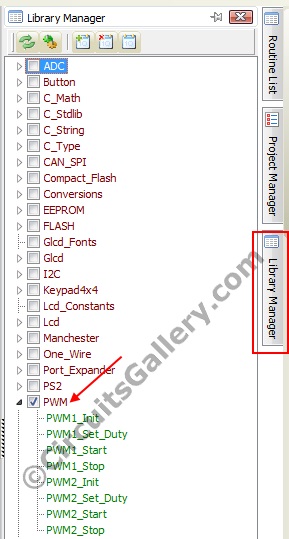
Before writing the program we should add PWM library functions to our code. Otherwise, you may be getting compilation errors such as ‘Undeclared identifier PWM1_Init in the expression’.
So open the ‘Library Manager’ tab and put a checkmark on the ‘PWM’ library. Then proceed to the program.
PWM Mikro C Program
In the program, two input switches are used to control the Duty cycle of the PWM signal. S1 for increasing the duty cycle and S2 for decreasing the same. The frequency of the PWM signal is set to 5KHz
Interpretation of important codes
PWM1_Init(5000)
There are two CCP modules inside PIC16F877A. Our program is manipulating the 1st module, thus ‘PWM1′ is used here. ‘_Init’ means initializing the PWM1 for 5KHz.
PWM1_Start()
Start PWM1 signal.
PWM1_Set_Duty(duty1)
Set the current duty cycle for PWM1, using this code we are varying the pulse width.
PWM Simulation in Proteus
Now it’s time to start the simulation, the Virtual Lab!
Step 1
Write the codes in Mikro C and build the. Hex file. If you don’t know how to build a hex file please read my article below.
Step 2
Run Proteus 8 and draw the schematic diagram as shown.
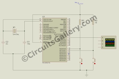
Step 3
Load .The hex file for PIC simulation.
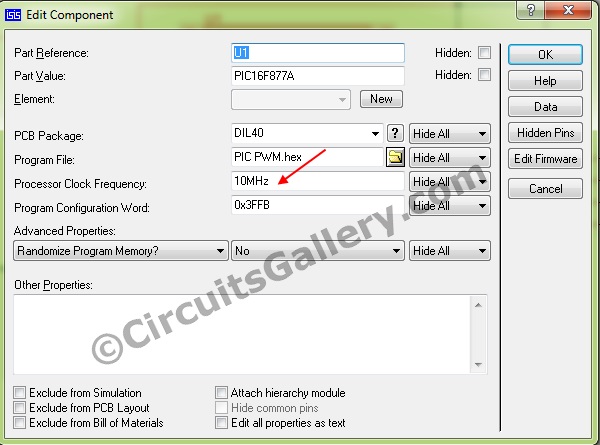
Step 4
Run the simulation.

Step 5
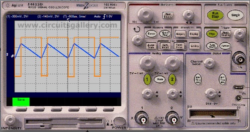
Enable Digital oscilloscope output by going to Debug >> Digital Oscilloscope and make necessary adjustments for a clear view.
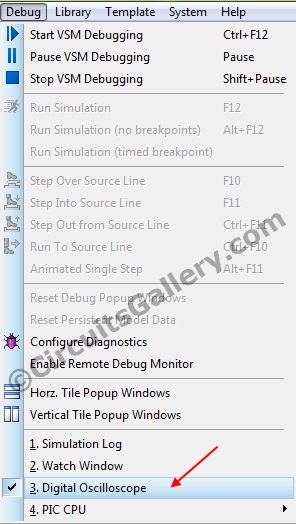
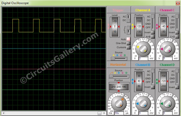
Step 6
Now vary the duty cycle by hitting the keys provided S1 and S2. The below image shows the simulated window of CRO.
So, that’s how you can generate a simple PWM (Pulse Width Modulation) signal. This signal is very handy and useful to modulate any input.
Conclusion
The output of PWM modulation is a duty-cycle varied square wave. In this article, we have demonstrated how the PWM Generator Circuit can generate waves using the 741 Op-Amp and provided the full MatLab code to generate a PWM signal. We also have described the generation of triangular waves the have significant applications in different electronic projects. You can easily generate this wave using the op-amp and the very simple circuit construction that is shown above. Finally, you’ve learned how to generate a simple PWM (Pulse Width Modulation) signal using microcontrollers. After all these, we hope, now you can make your own wave generator circuit without any problems. Best wishes for your upcoming PWM and triangular wave generator electronic projects.
Subscribe to our newsletter
& plug into
the world of circuits