Rotary Changeover Switch Wiring Diagram [Explained]
Rotary changeover switches are crucial parts in numerous electrical and electronic applications because they provide a smooth changeover between different electrical circuits or sources. These switches are frequently utilized in power distribution systems, industrial machines, and even home appliances.
A rotary changeover switch, also known as a cam switch or a selector switch, permits you to connect or disconnect one or more electrical circuits by rotating the switch handle.
In this article, we’ll discuss the specifics of rotary changeover switch wiring schematics, and step-by-step enlightening for establishment.
Basic Components of Rotary Changeover Switch Wiring Diagram
A rotary changeover switch wiring diagram includes:
1. Rotary Switch
This switch is indicated by an arrow in a circle around the central component. It connects a number of terminals in different areas.
2. Terminals
Wire connections and electrical flow are made possible by the switch’s identified terminals.
3. Connections and Wires
Lines represent the flow of electricity between terminals and parts, allowing the switch to operate.
4. Load Devices
The electrical components or loads that the switch regulates are typically represented by symbols or labels, making it clear what the switch controls.
5. Power Supply
The AC or DC electrical energy supply that powers the switch and any connected devices is shown in the diagram.
6. Grounding
Grounding symbols or connections are typically represented in diagrams for operational security.
7. Switch Positions
Due to the labeling of the switch’s positions and the wiring diagram’s depiction of the connections in each position, users may better understand how the rotary switch varies its configuration.
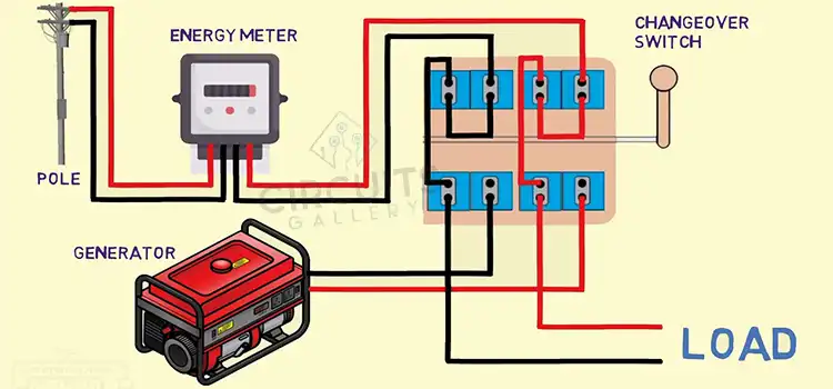
Circuit Diagram of Rotary Changeover Switch
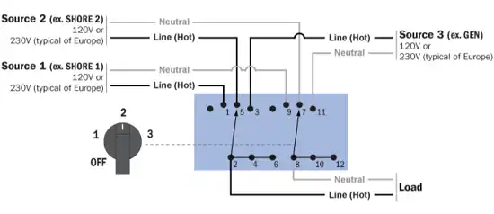
Image 1- Circuit Diagram of Rotary Changeover Switch
Step-by-Step Rotary Changeover Switch Wiring
To illustrate how to wire a rotary changeover switch, we’ll utilize a basic three-position switch as an example. Please be aware that different switch types may have somewhat different terminal setups; always refer to the manufacturer’s instructions for detailed information. These are the general steps:
1. Safety First
Before performing any electrical work, make sure the circuit’s power supply is turned off to prevent electrical accidents.
2. Examine the Switch
Learn where the switch’s terminals are marked. Terminals for rotating changeover switches are frequently labeled “A,” “B,” “C,” and so forth. Moreover, they might assign a number or letter (such as “1,” “2,” or “3”) to each site.
3. Identify the Circuits
Pick the circuits you want to connect utilizing the switch. For the sake of our example, let’s assume you have got three unique circuits: A, B, and C.
4. Connect the Power Source
The common power input terminal should be identified. This is usually denoted by “COM” or another similar title. To this terminal, connect the live wire or an additional power source.
5. Terminal Identification
For circuits A, B, and C, you must accurately match each switch position with the terminals (typically labeled as “1,” “2,” and “3”) in this step. Guarantee that the wires of each circuit are firmly connected to the appropriate terminal.
6. Verify the Wiring
After all connections have been made, it’s vital to verify your wiring again to make sure each circuit is accurately connected to the corresponding switch.
7. Secure the Connections
To guarantee safe and reliable connections, utilize the appropriate wire connectors or terminals to connect the wires to the switch terminals. Keep your connections secure to avoid compromising your framework.
Frequently Asked Questions and Answers (FAQs)
What are the Varieties of Rotary Switches?
Single-pole switches, which are utilized to control a single circuit, and multiple-pole switches, which are used to manage two or more circuits, are the two primary categories of rotary switches.
What Common Wiring Errors Should I Avoid?
Avoid making mistakes like misreading the wiring diagram, interfacing the wires to the inaccurate terminals, overloading the switch more than is advised, and incorrectly connecting the wires. You can prevent these issues by carefully following the diagram and performing careful connection testing.
Can I Combine Multiple Rotary Changeover Switches for Complex Setups?
Yes, you can make complex switching systems that rapidly switch between several circuits or power sources utilizing many Rotary Changeover Switches.
Conclusion
Switching between electrical circuits or power sources requires rotary changeover switches. Correct wiring is basic for both functionality and security. Follow the manufacturer’s instructions and the provided wiring diagram to guarantee a reliable installation. Prioritize safety and consult the switch’s particular documentation.
Subscribe to our newsletter
& plug into
the world of circuits