Siemens Contactor Wiring Diagram | A Detailed Wiring Guide
Siemens contactors are widely used for switching and controlling electrical loads, making them essential components in electrical control systems. Understanding how to correctly wire Siemens contactors is crucial to ensuring an efficient operation.
In this informative article, we will provide you with a thorough explanation of Siemens contactor wiring diagrams and how to implement them effectively.
Breaking Down the Wiring Diagrams of Siemens Contactors
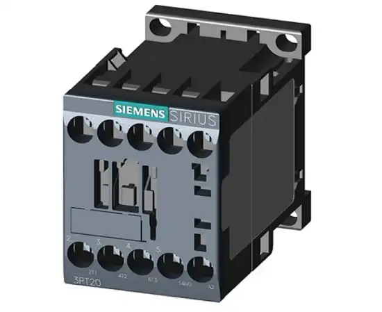
Figure: Siemens Contactor
Siemens contactors are widely used to establish or interrupt an electrical circuit. These components are frequently used in a variety of electrical applications, such as heating, lighting, and motor control. The Siemens contactor wiring diagrams include instructions on how to connect the various terminals. These diagrams are usually included in the product documentation.
Figure: Siemens Contactor Wiring
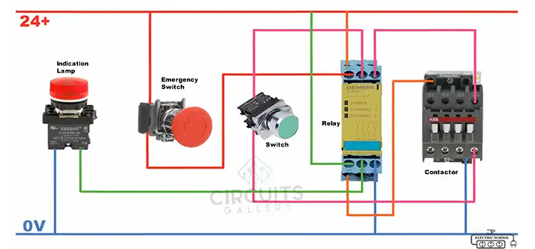
Identify the Contactor’s Terminals
Follow these instructions to properly identify the contactor’s terminals.
- Siemens Sirius contactor has two wire terminals, A1 and A2. This is where you connect a 24-volt DC power source to the coil to energize it.
- There are six additional wire terminals on the contactor’s opposite side. L1, L2, and L3 are written on the wire terminals at the top, going left to right.
- The bottom wire terminals are labeled T1, T2, and T3, going from left to right.
- The contactor’s L1, L2, and L3 terminals are used to connect the power wires, while the T1, T2, and T3 terminals are used to connect the device wires.
- The L1 contact is connected to the T1 contact, as are the L2 and T2 contacts, and the L3 and T3 contacts.
Wiring the Power Supply
To wire the power supplies, make sure to disconnect the power source first. Next, connect the main power supply lines (L1, L2, and L3) to the terminals on the contactor. You can use the wire strippers to remove insulation from the wire ends.
To control the load terminals, connect the load or the device you want (T1, T2, T3) to the contactor.
Testing and Troubleshooting
After completing the wiring, test the contactor to check that it operates correctly. Reconnect the power supply and activate the control voltage to see if the contactor switches the load on and off correctly.
Frequently Asked Questions and Answers – FAQs
How does a Siemens contactor work?
Answer: A contactor is a switch that can be controlled electrically and is used to switch an electrical power circuit. A contactor is typically controlled by a circuit that is much weaker than the switched circuit; for instance, we can control a 230-volt motor switch with a 24-volt coil electromagnet.
What are the main components of a contactor?
Answer: Any assembled electrical contactor device has three essential parts. These are normally the coil, the contacts, and the device enclosure.
What is the meaning of AC1 AC2 and AC3 in contactor?
Answer: AC1 refers to the non-inductive or slightly inductive rows, while AC2 indicates the Starting of slip-ring motors. AC3 in a contactor defines starting squirrel-cage motors and switching off only after the motor is up to speed.
To Conclude
While wiring Siemens contactors, make sure to use the correct wire size and type according to your application. Make sure to understand the wiring terminals properly before making any connections. To ensure its continued reliability, regularly inspect and maintain the device. Don’t hesitate to call in professional help if needed.
Subscribe to our newsletter
& plug into
the world of circuits