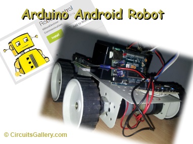
Arduino Project | Simple Arduino Robot Controlled by Android via Bluetooth Module HC-06/HC-05
Having posted some quality PIC microcontroller projects, I think now it’s time to take a break and have some great Arduino projects. Arduino project kits are becoming quite popular these days due to their advantages over other microcontroller systems. If you’re a newbie to Arduino then I strongly recommend you to read our article on getting started with Arduino.
Now let’s build an Arduino robot that can be controlled by an android mobile or tablet, with the help of an android app that can be downloaded from Google Playstore. The android application gets connected to the Bluetooth module and sends desired commands. This app-controlled robot is capable to move in any direction. Though there are lots of Robot control apps out there in the google play store to program with.
Components Required for Arduino Android Robot
- Arduino Board
- Robot Control Android App
- HC-06 Bluetooth module
- L293D IC
- 100 RPM DC motor X 2
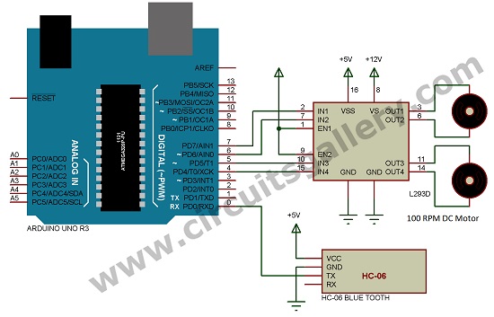
Arduino Project Circuit
Working Principle of Bluetooth Controlled Arduino Robot
- The TX pin of the HC-06 blue tooth module is connected to the RX pin (Pin 0) of the Arduino.
- Now the android application will connect the android device to Bluetooth module HC-06 or HC-05.
- You can scan the Bluetooth device ( HC-06 or HC-05) to connect using this application.
- After the connection has been established, you can start pressing buttons. When the forward button is pressed it will send letters ‘F’, ‘B’ for back, ‘R’ for right, ‘L’ for left, and ‘S’ for stop.
- Arduino will receive these letters via the serial pin RX of baud rate 9600.
- There are different program functions for forward, back, left, and right.
- After receiving data from the android device, Arduino switches the function corresponding to the letter received.
- Here I am using a 12V 100 RPM DC gear motor, so it can’t be driven by Arduino, I have used L293D to drive motors.
- The four pins of Arduino(4, 5, 6, and 7) are connected to the input pins of L293D for sending signals to drive the motor.
- By pressing the forward button on the android device, it will send an ‘F’ to the Bluetooth module which is received through RX (pin 0) of Arduino and it will store this into a variable ‘A’.
- Using the case statement it switches to the corresponding function, for forwarding movement both motors will rotate in the same direction, and to move it back both the motor will rotate in opposite directions to that of the forwarding direction.
- To move left and right either of the motors will rotate and stop both motors will stop.
- You can use either HC-06 or HC-05 Bluetooth module because here Bluetooth module acts as a slave, HC-05 can be used as master too but here we want to use it as a slave. You can buy a Bluetooth module for $10 approx.
- These modules are automatically enabled when you power up the device and you have to pair this with your android device using the default passkey 1234. You can change the name and passkey using AT commands.
Conclusion
We have recently introduced an obstacle avoidance robot using a PIC microcontroller. But this project itself is quite enough for beginners.
Subscribe to our newsletter
& plug into
the world of circuits