Simple Electronic Random Number Generator Circuit Using 555 and 4026 | Build a Simple Random Number Generator
Electronics is all about fun if you know how to enjoy it, you can make big things happen with simple logic. Here is another simple and entertaining circuit for electronic hobbyists. This simple game circuit will randomly generate a single-digit number upon pressing the push button.
You may predict a number and press the button and check if it’s correct or not. This can be helpful for lottery draws, lucky coupon draws, playing prediction games, and also other practical applications. This circuit has been prepared based on a request by one of our CG readers.
Before going onto the details, let me give you the simple idea behind the random number gen and it would be a lot better if you would have a look at our previous post on the 4026 digital counter circuit which is very much related. The main components used for our electronic random number generator hardware are the common 555 and 4026 ICs.
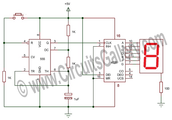
Circuit Diagram of Electronic Random Number Generator
Components Required for Making a Random Number Generator
- IC 555
- IC 4026
- Resistor (1K x3 )
- Capacitor (1uF)
- Seven segments (Common Cathode)
- Push-button
Working Principle of Random Number Generator Circuit
- The astable multivibrator using 555 timer IC will continuously generate square waves or pulses.
- The reset pin of 555 is connected to the ground through a 1K resistor to keep it in reset condition, so no pulses will be generated in this state.
- When the push button is pressed it will be activated and starts generating pulses.
- The output of the astable multivibrator is connected to the clock pin of the 4026 IC counter which will count the number of clock pulses.
- Here the frequency of pulses is so high that it can’t be seen on the display, to see if you have to stop the pulses.
- When you release the push button, the clock will stop and now you can see the current count. This is actually what happens here.
- As said earlier, you can increase the number of digits by cascading 4026.
Conclusion
We have a 555 timer IC configured in astable mode to supply very high-frequency clock pulses for the 4026, which is simply a decade counter IC for counting from 0-9. When the 555 clock is disabled with a push-button then it pauses the counting and displays the present count digit. Moreover, as explained in detail in our old 4026 counter circuit, you can extend the digits by increasing the 4026 IC and displays.
Subscribe to our newsletter
& plug into
the world of circuits