Simple Fire Alarm Circuit | Breakdown of Thermistor Circuit Diagram
Here Circuitsgallery comes with a simple and automatic fire alarm and detection system. This fire detection alarm circuit is based on the thermistor. A simple potential divider arrangement using a thermistor is capable of sensing the temperature (presence of fire) and alerting us with a warning signal.
This thermistor-based simple fire alarm circuit is suitable for your home security systems. Also, school students can do this fire detector circuit as their high school science fair project. Here I will explain in detail about fire alarm circuit wiring with animation/ simulation of a fire alarm.
What is a Thermistor?
A thermistor is nothing but a variable resistor whose resistance changes with temperature. Fire detection is simply possible via this low-cost alarm circuit.
Circuit Diagram of Simple Fire Alarm
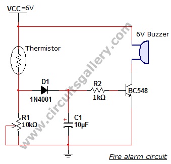
Components Required for Making a Simple Fire Alarm Circuit
- Power supply
- Resistors (1kΩ)
- Potentiometer (10KΩ)
- Capacitor (10µF, 16V)
- BC548 transistor
- High resistance thermistor (NTC)
- Diode (1N4001)
- 6V Buzzer
Working of Fire Alarm Circuit
- Working is based on the switching property of transistor.
- The thermistor and R1 forms a potential divider network which drives the transistor.
- The heart of this circuit is a thermistor. Thermistors are low-cost, easily-available temperature sensors widely used for uncomplicated temperature measurements.
- Thermistors are temperature sensitive resistors. When temperature increases resistance offered by the thermistor decreases and vice versa. At normal temperature, the resistance of the thermistor is around 10kΩ.
- All resistors vary with temperature, but the semiconductor materials used for thermistors are especially sensitive to temperature.
- The transistor is turned ON by the voltage drop across the resistor R1.
- Consider the temperature of the atmosphere is around 25°C, and then the resistance of thermistor is high so the voltage across the thermistor is also high according to the basic ohm’s law V=IR.
- The threshold voltage can be set by varying the potentiometer (R1).
- At this situation voltage across resistor R1 is low and it is not sufficient to turn on the transistor.
- As temperature rises, the resistance of thermistor decreases so that the drop across the resistor R1 increases which turns ON the transistor.
- When the transistor is turned ON, the current from Vcc starts to flow via 6V buzzer which produces a beep sound.
- Diode is used for enabling unidirectional conduction and the capacitor removes sudden transients from the thermistor.
Simulation of the Fire Alarm Project
We have used an LED instead of a buzzer for the simulation of the fire alarm system.
Conclusion
Many devices around us are constantly sensing the rise and fall of temperature. Almost all of them are using the Thermistor as the basis of this detection. Thus knowing its operation is quite pleasing to most electronics DIYers. Building a fire alarm circuit is, hence, much easier if you follow this guide.
Subscribe to our newsletter
& plug into
the world of circuits