Single Phase Drum Switch Wiring Diagram: A Comprehensive Guide
Single-phase drum switches play a crucial role in controlling the direction of rotation and the power flow in electric motors. These switches are commonly used in various applications, such as industrial machinery, garage door openers, and other equipment requiring reversible motor operations.
In this article, we’ll delve into the intricacies of single-phase drum switch wiring diagrams to help you understand how to properly set up and utilize these switches.
Components of a Drum Switch
Before diving into the wiring diagram, let’s familiarize ourselves with the main components of a single-phase drum switch:
- Rotary Switch: The core of the drum switch is the rotary switch, which consists of a rotating drum with various contact positions. These positions determine the electrical connections within the switch.
- Terminals: The switch has terminals labeled L1, L2, T1, T2, A, B, C, and so on. Understanding the purpose of each terminal is crucial for correct wiring.
- Wiring Diagram: A visual representation of the electrical connections required for the drum switch. This diagram guides users in connecting the switch to the power source and the motor.
Wiring Diagram for Single-Phase Drum Switch
The wiring of a drum switch will vary depending on the specific type of switch and motor being used. However, some general principles apply to all drum switch wiring. The first step is to identify the terminals on the drum switch. Most drum switches will have four terminals:
- L1: This is the input terminal for the power supply.
- L2: This is the output terminal for the power supply.
- T1: This is the terminal for the forward rotation of the motor.
- T2: This is the terminal for the reverse rotation of the motor.
The next step is to identify the terminals on the motor. Most single-phase motors will have three terminals:
- L: This is the input terminal for the power supply.
- N: This is the neutral terminal.
- T: This is the terminal for the start winding of the motor.
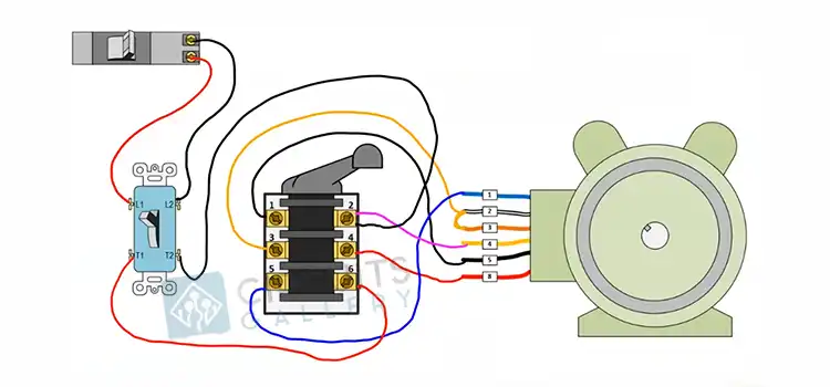
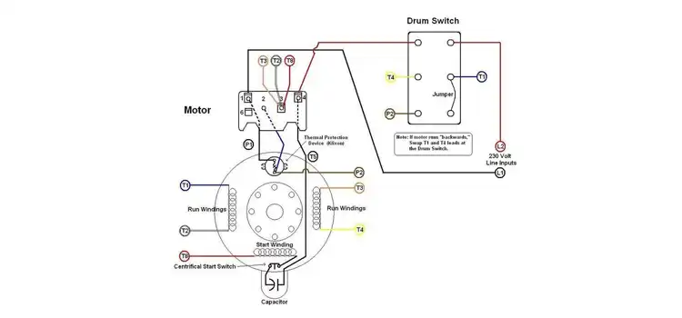
The following wiring diagram shows how to wire a single-phase drum switch to a single-phase motor:
We need to follow these steps to correctly wire a single-phase drum switch:
- Identify Power Source Wires: Determine the hot wire (L1) and the neutral wire. The hot wire is the live wire carrying the current to the switch.
- Connect Power Source Wires: Connect the hot wire (L1) to the L1 terminal on the drum switch and the neutral wire to the appropriate terminal.
- Connect Motor Wires: Connect the motor wires to the T1 and T2 terminals on the drum switch. The motor may have additional wires for capacitors or other features, depending on its design.
- Reversing the Motor: To enable motor reversal, connect additional wires from terminals A, B, and C on the drum switch to the corresponding motor wires.
- Grounding: Ensure proper grounding by connecting the ground wire to the designated terminal on the drum switch.

Safety Considerations
These are the safety things we need to consider while doing so.
- Disconnect Power: Before starting any wiring work, ensure that the power source is disconnected to prevent electrical accidents.
- Follow Manufacturer Guidelines: Always refer to the manufacturer’s instructions and guidelines for the specific drum switch model you are using.
Applications of Drum Switches
Drum switches are used in a wide variety of applications, including,
- Machine tools: Drum switches are used to control the direction of rotation of machine tool spindles.
- Conveyors: Drum switches are used to control the direction of movement of conveyor belts.
- Pumps: Drum switches are used to control the direction of rotation of pump shafts.
- Other industrial and commercial applications: Drum switches are also used in a variety of other industrial and commercial applications, such as on cranes, hoists, and elevators.
Benefits of Using Drum Switches
There are several benefits to using drum switches, including,
- Versatility: Drum switches can be used to control the direction of rotation of a variety of different types of motors, including single-phase, three-phase, and DC motors.
- Durability: Drum switches are built to withstand the harsh environments of industrial and commercial applications.
- Safety: Drum switches are designed to provide safe and reliable operation.
Frequently Asked Questions
Can I use a single-phase drum switch with any single-phase motor?
Generally, yes, but it’s crucial to check the motor’s specifications and follow the manufacturer’s guidelines for compatibility.
Can I wire a single-phase drum switch without electrical knowledge?
It’s possible, but basic electrical understanding is recommended. Follow the wiring diagram, and manufacturer’s instructions, and seek professional help if unsure.
Do wiring diagrams vary between different single-phase drum switch models?
Yes, always refer to the specific wiring diagram provided by the manufacturer for accurate installation, as diagrams can vary between models.
To Conclude
Drum switches are a versatile and durable type of electrical switch that is used to control the direction of rotation of electric motors. Drum switches are commonly used in industrial and commercial applications, such as on machine tools, conveyors, and pumps.
Subscribe to our newsletter
& plug into
the world of circuits