Squirrel Cage Fan Wiring Diagram | Learn How to Wire Your Fan with Ease!
The squirrel cage fan requires special wiring to function properly. The wiring diagram shows the fan regulator, switch, capacitor, and wire colors. Incoming hot wire, which is the black wire on the cord, is connected to the red wire. The 2nd and 3rd “unused” terminals are connected and tied through the #7 contact and #1 connector, respectively. Once these three are connected, the fan will run normally.
Squirrel-cage fans are widely applied in heating, ventilation, and air conditioning (HVAC) devices due to their lower noise compared to other types of fans in the same size. These are also known for their superior energy efficiency compared to other types of blowers.
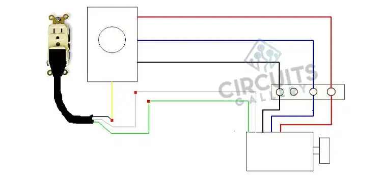
Wiring Diagram of Squirrel Cage Fan
A squirrel cage fan, also known as a centrifugal blower, is used to move air and gases in a variety of applications. This equipment is so named since its construction looks similar to that of a hamster wheel. These types of blowers use kinetic energy to increase the velocity and capacity of the air stream; thus differentiating them from positive displacement blowers, which use mechanical energy to physically move the air from the inlet to the outlet.
At the heart of the squirrel cage fan is an impeller, which is a circular or cylindrical mechanism with a series of curved vanes. As the impeller rotates, the air surrounding it also rotates at the same speed. This action imparts a centrifugal force to the air, causing it to move radially outwards to the walls of the blower or fan housing. The air follows a spiral trajectory – increasing in pressure and velocity – until it exits the discharge end of the blower.
How to Wire a 3 Wire Squirrel Cage Blower Motor
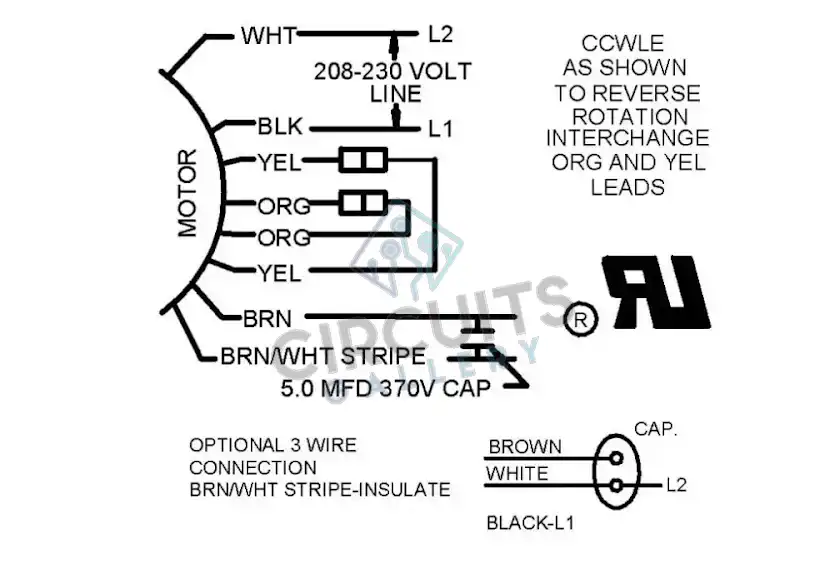
The wires shall be connected in a 3-wire blower motor following these procedures-
- White wire from the condenser fan motor to one side of power on the contactor (L2) and jumped to one side of the fan capacitor. This is AC power and not a dual capacitor, so the terminal side does not matter.
- Black wire from the condenser fan motor to the other side of power on the contactor (L1).
- Brown wire from the condenser fan motor to the other side of the capacitor opposite the jumper wire.
- Cap off brown + white (unused).
How Do You Wire a 2 Speed Squirrel Cage Fan
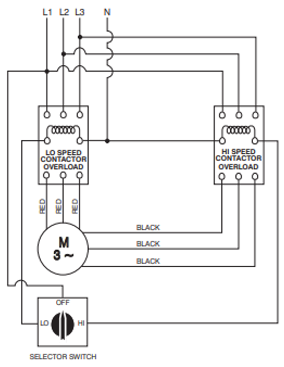
To properly set up this sort of high-low switch wiring, we’ll need an AC power supply, the two-speed motor, and a double-pole-double-throw switch. Most DPDT switches use three terminals because there will be a high-speed, low-speed and common wire hooked into them. A wire shall be attached between the common terminals of the AC power supply to the common terminal of the motor.
The black power supply shall be connected to the center terminal on the switch. Next, then a red wire will be used to connect the switch to the low-speed terminal of the motor. Then, a black wire will be used to connect the switch to the high-speed terminal of the motor.
We can now turn on the power to your motor and test that the switch works properly. The motor should run at low speed when the switch is flipped in the direction of the red-wired terminal and at a high speed when it is flipped in the direction of the black-wired terminal. If this is not the case, turn off the power. You will need to switch which wires go to which terminals so that they are properly arranged.
Wiring an Air Handler Squirrel Cage Fan Motor
An air handler fan motor basically has the feature of a single phase induction motor. A single phase motor has difficulty in providing a rotating magnetic field to start rotating the rotor. This is why the auxiliary winding is deployed to provide an additional magnetic field.
Adding another winding won’t help anything with rotating the rotor. A capacitor is used to shift the phase so we can get two rotating magnetic fields with different phases.
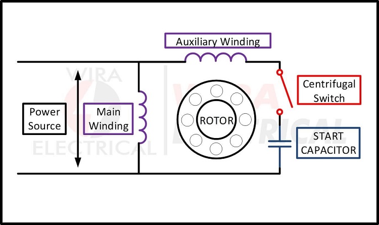
The following procedures must be followed to set up the wirings of single phase induction motor-
1. First, identify the starting winding and running winding terminals by measuring the resistance.
2. Connect any one terminal of each winding together, and it is to be connected to the neutral terminal of the power supply.
3. Connect the rest terminal of the running winding directly to the phase terminal of the power supply.
4. Connect the rest terminal of the starting winding to the phase terminal of the power supply through a series-connected capacitor.
Conclusion
Squirrel cage blowers are employed in a wide range of industrial applications due to their high efficiency and relatively low cost. They are typically used where a constant flow of large volumes of air is required, such as in ventilation, combustion, cooling and heating, drying, and air conveyor systems.
Subscribe to our newsletter
& plug into
the world of circuits