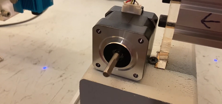
Stepper Motor Vibrating but Not Turning | Causes & Solutions
The motors will tremble and not turn if the appropriate stepper drivers are not providing enough current output. You should check your wiring as well. Ensure that all of your wires are connected and in the proper order. Typically, the stepper’s vibrating motor is caused by the stepper’s magnets firing in the wrong order.

Reason Why Stepper Motor Vibrating but Not Turning
It often happens that a motor vibrates but doesn’t rotate. The issue can lie in the power supply or the incorrect amount of Vref. Another common issue is incorrect connections.
Due to this, the motor vibrates front and back and turns a little bit backward and forward. Also, the coding error causes the stepping motor to simply vibrate and not rotate. Because the program pulse is delivered too quickly, the motor is unable to react and can only follow the vibration.
Another reason behind the stepping motor simply vibrating and not rotating is if the take-off frequency is too high or the load is too heavy and the motor’s output torque is insufficient.
Why Is My Stepper Motor Just Vibrating?
Due to the inertia of the moving rotor, stepper motors naturally vibrate somewhat with each step. As a result, the motor may occasionally overshoot (or undershoot) the step position and fluctuate until it “settles” at the proper step angle.
When a motor is operating with variable torque, torque ripple can cause the machine to vibrate a lot and make noise. The main source of noise and vibration from a stepper motor is torque ripple if the motor is not running at resonance.
Why Is My Stepper Motor Vibrating but Not Turning Arduino?
A standard code to operate a stepper is-
//Following is the code:
#define DIR_PIN 2 //STEPPER PIN
#define STEP_PIN 3 //STEPPER PIN
void setup() {
pinMode(DIR_PIN, OUTPUT);
pinMode(STEP_PIN, OUTPUT);
}
void loop(){
digitalWrite(DIR_PIN,HIGH);
for(int i=0; i < 100; i++){
digitalWrite(STEP_PIN, HIGH);
delayMicroseconds(1000);
digitalWrite(STEP_PIN, LOW);
delayMicroseconds(1000);
}
}
If running the code doesn’t give you a result, if the motor vibrates rather than rotates, there might be some issues with the wiring. The current flowing to the engine must be high if it’s becoming too heated.
Try reducing the potentiometer’s setting and then gradually increasing the current. Make that there are no loose or damaged connections between the board and the motor.
Why Isn’t My Stepper Motor Not Working?
A malfunctioning stepper motor driver or control board, a loss of continuity in the wire or a connector, or insufficient electrical current could all be the cause of a stepper motor’s malfunction.
Insufficient Current
You must first confirm that the motor is receiving an electrical current. You may try moving the motors from the menu by turning on the 3D printer; you don’t need a multimeter or any special tools for this.
Insufficient Voltage
While some printers only require 12V, some require 24V. At all times, the reading ought to be constant. The printer’s parts will start to malfunction if the power source terminals are not supplying the required voltage.
Incorrect Connection
The engine won’t run properly if one or more of the cables fails or if not connected properly. Replace the connector if you detect any wires that fail the continuity test.
Verify the Driver
The tiny board controls the stepper motor’s power and acts as a connector between the control board and the stepper motor. See if the issue is transmitted to the engine where you attached that driver by shifting the driver to a different plug.
The driver’s pins must be oriented appropriately when it is connected; look for the “Enable” pin on both the driver and the board and make sure they are the same. It will burn out the driver or control board if you turn it over.
How Do You Fix a Stepper Motor Vibration?
There are different causes of stepper motor vibration. The solution mostly depends on the cause behind it. Here are some solutions are given below.
Check the Circuit
Verify the motor phase line or wiring in accordance with the drawing if this is the initial wiring. If the stepping motor in use just vibrates and does not rotate, first determine whether the motor circuit is broken and unplugged.
If the stepping motor only vibrates and does not rotate, pay attention to the driver’s incorrect connection. The condition described will likewise occur if it is disconnected.
Check the Load
The motor can be disconnected from the load due to excessive load. Thus if the problem is in the load, just change it according to the requirement.
Check the Frequency of Input Pulse
Stepper motor input frequency must not be excessively high. If the higher input frequency is the reason, lower the input frequency as needed.
Conclusion
Stepper motor malfunction is a common thing to deal with. If you own a stepper motor, you may face the problem of its vibrating but not rotating at least once. The reasons are common as well and the solution is also not difficult to find. If the problem occurs, try to find the cause from the ones mentioned above and proceed thereby.
Subscribe to our newsletter
& plug into
the world of circuits