Street Light Wiring Diagram | Complete Guide to Street Light Wiring
Streetlights are essential in order to ensure security, visibility, and beauty on the roads of both cities and the countryside. They’re making the city prettier and helping to avoid accidents throughout the night. In order to guarantee the smooth functioning of these devices, a clear definition of their wiring system is essential.
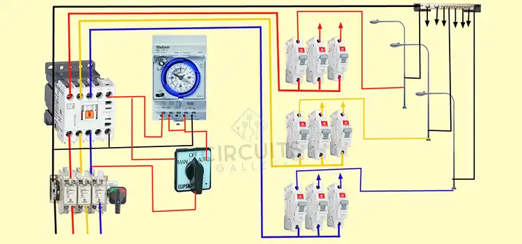
The following article will give you a clear idea of the schematic of street lights, including components such as the MCB, RCCB, relay, timer, and selector switches. Let’s delve further into this topic!
Required Components Needed for Wiring Street Light
MCB (Miniature Circuit Breaker): Acts as an assurance device that consequently stops the flow of current in case of a short circuit or overload.
RCCB (Residual Current Circuit Breaker): Guarantees safety against electric shocks by identifying any imbalance between live and neutral wires, cutting off the power quickly.
Relay: A switch operated by an electromagnet for opening or closing one or several sets of contacts.
Timer: used to operate the street lights by chance, for a specific time, or under special lighting conditions.
Selector switch: Provides manual control for turning on, off, or changing the working mode between distinctive operating modes.
Wiring Procedure of Street Lights
We’re already familiar with the components needed for street light wiring. Now, let’s check out the connections between them.
Connection of MCB and RCCB
Start with the main power source. Connect the incoming phase and neutral lines to the RCCB. Right now, the operational terminals of the RCCB are connected to the MCB. Both RCCBs and MCBs are designed to protect against any electric shock that might occur, guaranteeing the security of overloads and short circuits.
Incorporating the Timer
The timer is an important device in the automation process. Interface the active phase of the MCB to the timer’s input. For street lights, set a timer according to the specified on and off times. The relay will be supported by the timer’s output, ensuring that the lights are turned on and off at the indicated time.
Relay Connection
Connect the timer’s output to the relay’s coil. The relay acts as a programmed switch that turns on or off based on the signal from the timer. The relay’s Normally Open (NO) terminal will interface with the phase line of the street light. The neutral line of the street light connects directly to the main neutral.

Figure 01: Street Line Wiring Diagram
Measures Related to Security and Safety
- Before you work on the electrical cable, make sure that it is turned off.
- In order to prevent loose connections from leading to short circuits, guarantee that all associations are tight and secure.
- Always check the wire for wear and tear, particularly when road lights are located in areas with harsh weather conditions.
- Coordinate the specifications of street lamps using components such as MCB, RCCB, and Relay to take account of their voltage and power ratings.
Advantages
Safety
The MCB and RCCB’s incorporation offer protection against overloads, short circuits, and electric shocks.
Flexibility
The selector switch for manual intervention if necessary provides flexibility in operation.
Energy Efficiency
The timer enables the street lights to be turned on only during the appropriate hours, resulting in energy savings.
Frequently Asked Questions and Answers
1. How are street lights connected?
Streetlights are connected in parallel. This is because if we connect them in series, the voltage across each light would drop, causing it to glow less brightly than it should. So, to maintain rated voltage across each light, we have to connect them in parallel.
2. Do street lights come with a switch?
Streetlights in a particular area or along a specific street are generally activated or deactivated simultaneously through a central switch. Nevertheless, switches that are time-based may not be suitable for directly managing high-powered electrical devices.
3. How are modern streetlights controlled?
Smart technologies are frequently used in present-day streetlights. This can comprise:
Remote monitoring and control: Central systems are able to keep track of each light’s condition and make remote alterations.
Intelligent lighting: The brightness can be changed according to the time of day or the flow of traffic.
Energy conservation: When there’s no movement within the area, certain systems can dim or turn off the lights.
Conclusion
A well-designed wiring arrangement for street lights guarantees their advantageous and secure operation. By combining components like MCB, RCCB, Relay, Timer, and Selector Switch, it is possible to function road lighting with automation, flexibility, and security. Regular maintenance and assessments are vital to ensuring the life span and effective performance of the system.
I hope you get the basic idea of street light wiring by reading this article. Good luck with your project!
Subscribe to our newsletter
& plug into
the world of circuits