Summing Amplifier – Inverting Adder Circuit Using Op Amp 741
A summing amplifier or an adder is used to sum two signal voltages. A voltage adder circuit is a simple circuit that enables you to add several signals together. It has a wide variety of applications in electronic circuits. For example, on a precision amplifier, you may need to add a small voltage to cancel the offset error of the op-amp itself. An audio mixer is another good example of adding waveforms (sounds) together from different channels (vocals, instruments) before sending the combined signal to a recorder. You can change the gain or add another input without messing up with the gains of other inputs. Just remember that the inverting summing amplifier circuit inverts the input signals. That’s not a big deal. If you need the opposite polarity, all you have to do is to put an inverting stage before or after the summer.
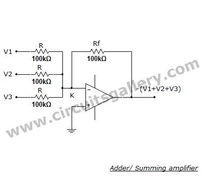
Circuit Diagram of Adder/Summing Amplifier
Components Required for Wiring Summing Amplifier
- Power supply
- IC 741 Op-Amp
- Resistors (100kx4)
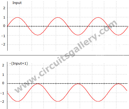
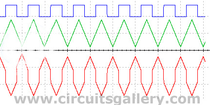
Output waveform of Summing Amplifier
Adding one sine wave and DC voltage
Adding two different waveforms
Working Procedure of Summing Amplifier
- Here the input voltages V1, V2, and V3 are given into the adder circuit.
- This is an inverting summing amplifier because the output is the sum of inputs with a significant change.
- To construct a noninverting adder, you can cascade one ‘Inverting amplifier with unity gain along with this circuit.
- The output of this adder circuit is given by – (V1+V2+V3).
- Consider the current flowing through the input resistors are
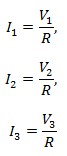
- Then by Kirchoff’s current law, the current flowing through feedback resistor Rf is given by the sum of these 3 currents.
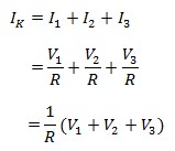
- This current will flows through the feedback resistor Rf because the point ‘K’ acts as a virtual ground point. So the voltage drop at Rf is given by
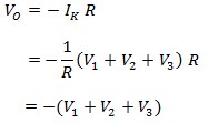
- -ve sign is due to the op-amp connected in inverting mode.
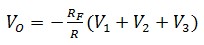
- This circuit is called a summing ‘amplifier’ because it can provide gain. By adjusting the value of Rf the gain can be changed.
- Then the output becomes
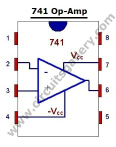
Components pinout
Conclusion
Using a summing amplifier is one of the important parts of any kind of project. By following the above tutorial, you can easily make your own one using a simple op-amp 741.
Subscribe to our newsletter
& plug into
the world of circuits