Three-Phase Air Compressor Motor Starter Wiring Diagram | A Complete Guide
A motor starter provides controlled 3-phase power connectivity between the breaker panel and the air compressor motor. It safely manages large currents to protect the motor from damage while allowing it to be turned on/off from remote stations.
Here I will discuss the wiring diagram of a 3-phase air compressor motor, providing a comprehensive guide to understanding and connecting the electrical components involved.
Components of a 3-Phase Motor Starter
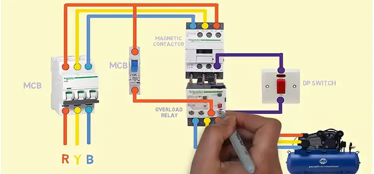
A 3-phase motor starter serves as an intermediary between the power supply and the air compressor motor, controlling the flow of electricity and ensuring the motor starts and operates smoothly. The core components of a 3-phase motor starter include:
- Contactor: An electromagnetic switch that controls the flow of electricity to the motor.
- Overload Relay: A protective device that safeguards the motor from excessive current and potential damage.
- Control Circuit: A set of electrical components that control the operation of the contactor and overload relay.
- Start Button: A pushbutton that initiates the starting sequence of the motor.
- Stop Button: A pushbutton that immediately disconnects power to the motor.’
- Pressure Switch: A pressure switch is a safety device that shuts off a three-phase air compressor motor when the pressure in the tank reaches a certain level.
Wiring Diagram of Three-Phase Air Compressor Motor Starter
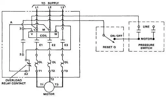
Terminal Identification of Motor Starter
- L1, L2, L3: Three-phase power supply terminals
- E1, E2, E3: Overload relay terminals
- T1, T2, T3: Motor leads terminals
- OL: Overload relay contact
- X1/X2: Start button terminal
- A1/A2: Contactor coil terminal
- VMW: Variable motor winding terminal (optional)
Wiring Procedure of Motor Starter in 3-Phase Air Compressor
The following steps show the wiring procedure steps for the phase air compressor motor starter:
- Mount starter/verify dimensions
- Remove cover safety procedures
- Identify terminals/wiring labels
- Connect L1, L2, L3 power lines
- Connect T1, T2, T3 motor lines
- Wire overload relay sensors
- Connect external start/stop stations
- Connect control transformer outputs
- Verify tight terminal screw connections
Operation of Starter In 3-Phase Air Compressor
When the start button (X2) is pressed, the contactor coil (A) is energized, which closes the main contactor contacts. This connects the motor leads (M1, M2, and M3) to the power supply, starting the motor. The overload relay monitors the motor current and disconnects the power supply if the current exceeds a safe threshold.
Testing and Commissioning of Starter Connection
Energize the control circuit and use external stations to turn the motor ON/OFF. Check:
- Smooth starting torque/low current surges
- Correct rotation direction
- Rated load current not exceeded
Use a phase rotation meter if rotation is incorrect. Carefully uncouple the compressor only after completing tests.
Troubleshooting Starter Connection
If the motor does not start when the start button is pressed, check the following:
- Is the power supply turned on?
- Are the connections between the power supply, the contactor, the overload relay, and the motor secure?
- Is the overload relay contact closed?
- Is the contactor coil energized?
If the motor starts but then trips the overload relay, check the following:
- Is the motor properly sized for the load?
- Is the motor properly ventilated?
- Is the motor overloaded?
- Is the overload relay set to the correct current rating?
FAQs – Frequently Asked Questions and Answers
- How to reverse a 3-phase motor rotation direction?
Answer: Interchange any two of the T1, T2, T3 motor power leads.
- Why the need for a separate control circuit?
Answer: It allows remote control stations and protects against short circuits.
- Can a 3-phase motor work if one phase is lost?
Answer: No, all 3-phases must be connected for proper balanced operation.
Correct wiring of 3-phase air compressor motor starters is critical for reliable and safe functionality. Follow the guidelines above for trouble-free operation over years of service.
To Conclude
Understanding starter wiring diagrams and step-by-step installation guidelines ensures correct building connections. Taking safety precautions like locking out power sources and verifying the circuit prevents mishaps. Proper starter wiring provides a robust and reliable interface for efficient compressed air generation over years of rigorous industrial use.
- Components of a 3-Phase Motor Starter
- Wiring Diagram of Three-Phase Air Compressor Motor Starter
- Terminal Identification of Motor Starter
- Wiring Procedure of Motor Starter in 3-Phase Air Compressor
- Operation of Starter In 3-Phase Air Compressor
- Testing and Commissioning of Starter Connection
- Troubleshooting Starter Connection
- FAQs - Frequently Asked Questions and Answers
- To Conclude
Subscribe to our newsletter
& plug into
the world of circuits