Water Flow Switch Wiring Diagram | A Complete Guide
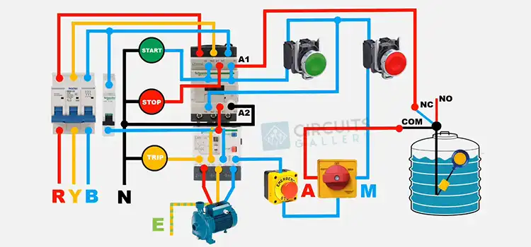
The Water Flow Switch Wiring Diagram consists of five terminals, each designated by a specific color and function. L1 (Red) serves as the incoming power line, while L2 (Red) is the outgoing power line connected to the controlled device. N (Black) represents the neutral line, E (Green) is for the protective earth wire, and S (Blue) designates the water flow switch terminal linked to the controlled device.
You should adjust flow sensitivity, verify secure connections, and then restore power to test the switch operation at different flow rates. Proceed from here to have a better idea.
Water Flow Switch Wiring Diagram
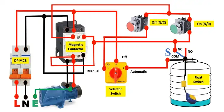
The following diagram shows a typical wiring diagram for a Water Flow Switch Wiring Diagram:
Terminal Identification of Water Flow Switch Wiring
The following table shows terminal markings, color, and their name:
| Terminal | Wire Color | Function |
| L1 | Red | Incoming power line |
| L2 | Red | Outgoing power line |
| N | Black | Neutral line |
| E | Green | Protective earth wire |
| S | Blue | Water flow switch terminal |
Wiring Connection of Water Flow Switch Wiring
Here is a detailed explanation of the wiring connections for a water flow switch:
- L1 terminal: The L1 terminal is the incoming power line terminal. This terminal is connected to the power source that will be supplying power to the water flow switch and the control device.
- L2 terminal: The L2 terminal is the outgoing power line terminal. This terminal is connected to the control device that the water flow switch is controlling.
- N terminal: The N terminal is the neutral line terminal. This terminal is connected to the neutral wire of the power source.
- E terminal: The E terminal is the protective earth wire terminal. This terminal is connected to the protective earth wire of the power source.
- S terminal: The S terminal is the water flow switch terminal. This terminal is connected to the control device that the water flow switch is controlling.
Step-by-Step Wiring Procedure of a Water Flow Switch
Follow these steps to wire a Water Flow Switch Wiring Diagram:
- Connect Power Lines: Attach L1 and L2 power lines to the terminals.
- Connect Neutral and Ground: Link neutral (N) and ground (E) wires.
- Connect Flow Switch Terminal: Attach the S terminal to the monitoring system.
- Set Flow Sensitivity: Adjust the flow sensitivity as needed.
- Verify Connections: Confirm all wiring connections are secure.
- Restore Power: Power up and test switch operation at various flow rates.
Troubleshooting and Safety: Water Flow Switches
To troubleshoot water flow switch issues, check power supply and wire connections, clean any dirt on the switch, and replace it if problems persist. Prioritize safety by disconnecting power before wiring, using suitable wire gauges and connectors, and testing the switch post-wiring to ensure proper functionality.
FAQs – Frequently Asked Questions and Answers
- What is the difference between a water flow switch and a water pressure switch?
Answer: A water flow switch senses the flow of water through a pipe, while a water pressure switch senses the pressure of the water in a pipe.
- When should a water flow switch be used?
Answer: Water flow switches are used in a variety of applications, such as to prevent pumps from running dry, to protect boilers from overheating, and to activate alarms in the event of a leak.
- How do I test a water flow switch?
Answer: To test a water flow switch, you can use a multimeter to measure the voltage at the terminals. If the voltage is present when the water is flowing, and the voltage is not present when the water is not flowing, then the water flow switch is working properly.
To Conclude
This guide covers the key aspects of wiring water flow switches- identifying terminals, wiring diagrams, safety, and correct installation steps. Paying attention to these details will ensure your flow monitoring system works reliably. Use the resources here as a reference to wire water flow switches with confidence.
Subscribe to our newsletter
& plug into
the world of circuits