Skip to content
Circuits Gallery
  • Home
  • BasicsExpand
    • Wiring
    • Op-Amp
    • Circuitry
    • Oscilloscope
    • Conductivity
    • Components
  • MicroControllerExpand
    • Arduino
    • PIC
    • Simulation
  • ProjectExpand
    • Using 555 Timer
  • DigitalExpand
    • Communication
  • Submit Project
Circuits Gallery
Home / Basics / Wiring / WH5 120 L Wiring Diagram | Explained

WH5 120 L Wiring Diagram | Explained

The WH5 120L, a versatile ballast by Fulham Co., Inc., requires correct wiring for optimal performance. Its diagram uses symbols like L (hot wire), N (neutral), G (ground), and R, Y, B, and W for specific wires. 

The specific wiring configuration depends on the number and type of lamps used. For example, two F32T8 lamps require a different wiring layout than a single F54T5HO lamp. Always consult the WH5 120L’s spec sheet and local electrical codes before installation. 

WH5 120 L Wiring Diagram

Wiring Diagram of WH5 120 L

Analyzing the diagram allows us to understand the circuit layout, wire sizing, conduit requirements, and grounding connections. This ensures a safe and functional installation. The specific configuration will vary depending on the number and type of lamps used.

Wiring Diagram of WH5 120 L

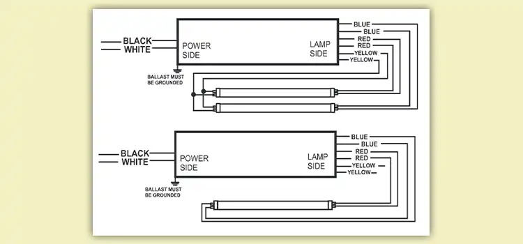
Figure 1: WH5 120 L Wiring Diagram

  1. AC Power Input:
  • The ballast requires a 120-volt AC power supply.
  • Terminals for AC input may be labeled as Line (L) and Neutral (N).
  • There might be additional terminals for connecting to the incoming power source.
  1. Lamp Connections:

Fulham WorkHorse 5 is designed for four lamps.

  • The lamp connections will typically have multiple pairs of terminals, each corresponding to a specific lamp.
  • Terminals may be labeled as follows: Lamp 1 (L1), Lamp 2 (L2), Lamp 3 (L3), and Lamp 4 (L4).
  1. Grounding (if applicable):
  • Some ballasts may have terminals for grounding. Ensure proper grounding as per local electrical codes.
  1. Other Features:
  • The ballast may include additional features such as an emergency backup battery connection, if it supports emergency lighting.

Frequently Asked Questions

What symbols are used in the WH5 120L wiring diagram?

Common symbols include L (line), N (neutral), G (ground), R (red output), Y (yellow output), B (black input), and W (white input). Each symbol represents a specific wire and its function.

How do I know which wiring configuration is right for my setup?

The specific configuration depends on the number and type of lamps you are using. The WH5 120L supports various lamp combinations, each requiring different wiring arrangements. Refer to the diagram or spec sheet for specific instructions.

Can I use any type of wire with the WH5 120L?

No, you must choose the appropriate wire gauge based on the circuit length and load. Using undersized wires can pose safety hazards due to overheating.

Conclusion

Always comply with local electrical codes and regulations. Use the correct lamp type and wattage specified for the WH5 120L. Prioritize safety and consult a professional if you have any doubts or require assistance with the installation or operation of the ballast.

Table Of Contents
  1. Wiring Diagram of WH5 120 L
  2. Frequently Asked Questions
  3. Conclusion

Subscribe to our newsletter

& plug into

the world of circuits

    A seasoned electronics enthusiast, Charles Clark is a key contributor to Circuits Gallery. From basic components to advanced microcontroller projects, Charles simplifies complex concepts with ease. His writings are a blend of expertise and passion, making electronics accessible to all. Whether it's circuitry or digital communication, Charles is the voice you can trust.

    Facebook Twitter Instagram

    Recent Blogs

    • How to Make A 75 To 300 Ohm Matching Transformer
      How to Make A 75 To 300 Ohm Matching Transformer? | A Step by Step Guide for You
    • How to Download Circuit Wizard? | Procedure for Downloading the Latest Version
    • What Gauge Wire from Battery to Starter
      What Gauge Wire from Battery to Starter? | Choosing the Right Wire Gauge
    • What Does 50 Milliamps Look Like on a Multimeter
      What Does 50 Milliamps Look Like on a Multimeter? | Let’s Find Out
    • How Many Watts Does a 32 Inch TV Use
      How Many Watts Does a 32 Inch TV Use? | Find Out the Required Wattage for Different Brands
    • What Size Conduit for 122 Wire
      What Size Conduit for 12/2 Wire? | Choosing the Right Conduit for Your 12/2 Wire

    Browse Categories

    • Arduino
    • Basics
    • Circuitry
    • Communication
    • Components
    • Conductivity
    • Digital
    • How To
    • MicroController
    • Op-Amp
    • Oscilloscope
    • PIC
    • Project
    • Simulation
    • Using 555 Timer
    • Wiring
    Circuits Gallery
    Join Our Community:

    Quick Links

    • About Us
    • Privacy Policy
    • Terms and Conditions
    • Submit Your Project
    • Contact Us

    Our Story

    Our journey designing innovative devices had immersed us in convoluted electronics. We realized mastery doesn't require elite degrees or industry secrets—just knowledge presented coherently. We became devoted to unraveling even quantum-complex circuits, diagram by diagram, so anyone eager to learn can unlock these secrets. By simplifying electronics fundamentals, we hope to ignite innovation in generations to come.

    © Copyright 2025 Circuits Gallery | All Rights Reserved.

    • Home
    • Basics
      • Wiring
      • Op-Amp
      • Circuitry
      • Oscilloscope
      • Conductivity
      • Components
    • MicroController
      • Arduino
      • PIC
      • Simulation
    • Project
      • Using 555 Timer
    • Digital
      • Communication
    • Submit Project
    Search