What Causes Voltage on Ground Wire? 8 Probable Issues
Electricity powers homes, businesses, and technology requiring grounding for stability and safety. Voltage on ground wires can be fascinating and perplexing. This can happen due to stray currents, undersized neutral connections, or due to EMF or capacitive coupling.
This article examines the complexities of this mystery and the possible origins of voltage on ground lines.
Voltage on Ground Wires | Reasons Behind That
Grounding is a crucial safety measure in electrical systems, providing a current return path in case of short circuits. For household appliances, it is achieved through a three-pronged outlet with a dedicated grounding prong. In some transmission systems, grounding acts as an extended neutral line, providing electrons for the generator and endpoints for electrons after the load.

However, this use is only available in Single Wire Earth Return transmission systems, mainly used in rural areas like Canada and Australia. Most modern transmission systems use three-phase electric power, which does not use grounding as a return path.
Grounding aims for zero potential reference points, but ground lines may display voltages that contradict this goal, causing confusion and unsettling effects. Voltage on ground lines can have several possible reasons, each connected to different elements in electrical systems.
1. Electromagnetic Interference (EMI)
Electromagnetic interference (EMI) is one of the frequent motives why there’s voltage on the floor wires. This occurs while neighboring equipment, energy traces, radio waves, or other outside electromagnetic fields generate voltage onto ground wires. These electromagnetic impulses are by chance picked up and carried down the circuit through the ground twine, which serves as an inadvertent antenna.
2. Capacitive Coupling
Capacitive coupling, in which two conductive surfaces separated by using an insulator create an electric discipline, can also lead to voltage on ground wires. When a voltage difference exists between these surfaces, a small amount of modern flows via the insulator, inducing voltage on the floor wire.
This can occur whilst there are close-by high-voltage strength lines or gadgets with unbalanced voltages.
3. Stray Currents and Faults
Stray voltage happens when an electrical leak from a hot twine to an impartial wire causes a quick circuit in an electrical gadget. This can cause electrocution if the floor wire is touched, causing capacity damage to the system.
4. Inductive Coupling
Inductive coupling consists of the go with the energy flow among two carrying out additives, much like capacitive coupling does. In this instance, magnetic fields are used. A ground wire can also revel in a voltage spike if it’s far positioned adjoining to a modern-day-carrying conductor because of the conductor’s moving magnetic discipline.
5. N-G voltage on voltage drops
Ground wires may receive power from N-G voltage whilst voltage decreases due to extended copper wires. The high load can motivate voltage drop in impartial wire, main to N-G voltage, and floor twine electricity.
6. Undersized neutral connection
Three-segment circuits are commonplace in business structures, however insufficient neutral connections can cause imbalances in modern infrastructure, inflicting strong currents and the impartial ground voltage.
7. Tying ground and neutral together
Neutral wires carry cutting-edge from warm wires to major power, while ground wires lack energy. Connecting a neutral cord to a ground cord energizes grounding, but it doesn’t serve its cause and may cause electric shocks, mainly if the appliance is faulty.
8. Corroded earth connection
Find corroded earth connections if the ground cable is powered. The ground wire may also get electricity via loose ground connections, damaged electrical boxes, and conduits.
Checking for Voltage on the Ground Wire
To know whether there is voltage on the ground wire, we would have to test it.
1. Simple Method
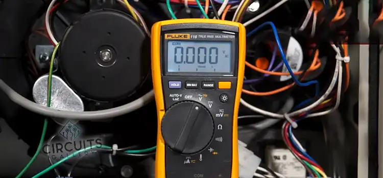
Use a voltmeter or multimeter to check ground wire voltage. Set AC voltage range to 200-240 volts. Place probes on neutral and ground wires, and check for non-zero readings.
2. Alternative Method
Here is another method you can use. Follow these steps in order:
- Set the voltmeter or multimeter to AC with the cutoff set at the highest value. Connect the red and black leads to the positive (+) and COM ports, inserting them into the hot/live and neutral slots. Note the readings, which should be close to the supply voltage of 240 volts.
- Connect the red probe to the earth/ground slot and take another reading, ensuring the final reading is no more than 5 volts. Connect the black probe to the neutral and the red probe to the ground slot. If you live in the USA, you should get these results to confirm that the ground has no voltage (permitting a 5% deviation):
Live/Hot with Neutral = ~ 120 volts
Live/Hot with Ground/Earth = ~120 volts
Neutral with Ground/Earth = ~0 volts
Frequently Asked Questions and Answers – FAQs
What to do if the ground wire has too much power?
Ground wires should not have power or current unless there is a short circuit or a connection with hot or neutral wires. If a fault occurs, an experienced electrician can identify and fix the issue. They can find improper grounding, corroded, and neutral or hot wire connections. Using a multimeter, the electrician can identify and confirm the issue, ensuring a quick and safe solution.
What Voltage Is Normal and When Should I Worry?
You shouldn’t be concerned about two volts or less. Your readings should only cause you concern if they go over the predicted level. N-G voltage is more than just a hassle.
Why do I have current on the ground wire?
Ground currents can be worsened by several electrical issues in the user’s electrical systems. Some of these issues include electrical flaws, electrical system imbalances caused by the user, motor malfunctions, and wiring mistakes.
To Conclude
Voltage on ground wires in electrical systems is a complex issue that can result from external factors like electromagnetic interference, capacitive coupling, ground loops, and stray currents. Understanding these causes helps engineers and technicians tackle these issues effectively, ensuring reliable electricity flow in modern times.
Subscribe to our newsletter
& plug into
the world of circuits