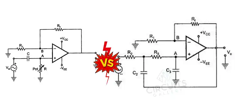
What is the Difference Between First Order and Second Order Active Filters? Important Aspects to Know
Active filters are crucial in electronics and signal processing for modifying and shaping electrical signals. They can amplify and attenuate frequencies, with first-order and second-order filters having distinct properties.
Understanding these filters is essential for selecting the best solution for electronic design issues. In this article, we’ll explore the distinctions between them and discover.
Definition of First-Order and Second-Order Active Filters
Before delving into the differences, let’s establish what first-order and second-order active filters are.
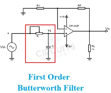
First-Order Active Filters
A first-order active filter is an electrical circuit that modifies the frequency response of an input signal using active components like op-amps and passive components like resistors and capacitors. These filters highlight or attenuate specific frequency components, while others pass through untouched. The term “first-order” refers to the filter’s transfer function, which is a mathematical representation of how it handles incoming signal frequency components.
Roll-Off Rate
First-order filters have a roll-off rate of 6 dB per octave, meaning the filter’s gain (or attenuation) changes by 6 dB for every doubling (or halving) of frequency. This results in a relatively gradual transition between the passband (where frequencies are allowed to pass) and the stopband (where frequencies are attenuated).
First-order filters cause a frequency-dependent phase shift in the signal, impacting phase relationships between frequency components. These simple, frequency-dependent filters require only one reactive component, typically a capacitor, in addition to resistors and op-amps.
Applications
First-order active filters are used in audio systems for tone control, signal conditioning, and removing high-frequency noise. They have lower order and gradual roll-off, allowing smoother transitional behavior between passband and stopband, reducing unwanted artifacts in applications with moderate frequency selectivity.
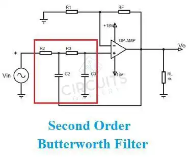
Second-Order Active Filters
A second-order active filter is an electrical circuit that modifies the frequency response of an input signal utilizing operational amplifiers, reactive components, and resistive components. It emphasizes or attenuates specific frequency components while allowing others to pass through unaffected. The word “second-order” denotes the transfer function, a second-degree polynomial in the frequency variable, which denotes the mathematical representation of the frequency components of the input signal by the filter.
Roll-Off Rate
In comparison to first-order filters, second-order filters have a sharper roll-off rate. They reduce frequencies by 12 dB per octave, which makes the shift between the passband and the stopband more noticeable.
Second-order filters provide better selectivity in passing desirable frequencies while providing more attenuation of undesired frequencies due to their higher order. They are therefore appropriate for uses that call for precise frequency control.
They introduce a phase shift in signal, pronounced near cut-off frequency, and are more complex to design and implement than first-order filters due to the use of reactive components and resistors.
Applications
Second-order filters have larger Q factors and resonance at certain frequencies, which makes them excellent for oscillator and audio equalization circuits. They are helpful in audio processing, communication systems, and control systems due to their increased attenuation, sharper roll-offs, and improved selectivity.
Distinguishing Factors between First Order and Second Order Active Filters
| Aspects | Difference Between Them |
| 1. Roll-Off Rate | The roll-off rate is the crucial difference between first-order and second-order active filters. In comparison to a first-order filter, a second-order filter may attenuate frequencies more quickly as frequency increases because of its higher roll-off rate. |
| 2. Attenuation and Selectivity | Due to their steeper roll-off, second-order filters provide more control over signal processing. This corresponds to enhanced selectivity in passing desirable frequencies and better attenuation of undesired frequencies. |
| 3. Phase Shift | In comparison to second-order filters, first-order filters introduce less phase shift into the passband. This phase shift may be significant in applications, such as audio systems, where maintaining signal phase relationships is essential. |
| 4. Components Complexity | Second-order filters are a little more difficult to design and execute than first-order filters because they employ more components (two reactive components) than first-order filters. Nevertheless, this complexity frequently results in better performance. |
| 5. Resonance and Q Factor | Resonance is a property of second-order filters that can be useful in systems like oscillator circuits or audio equalization. For second-order filters, the Q factor, which measures the quality of resonance, is greater. |
| 6. Transient Response | Due to their more straightforward construction, first-order filters typically offer a quicker transient response. This might be helpful in situations where it’s important to correctly follow quick changes in input signals. |
Application Considerations
Depending on the requirements of the individual application, one should choose between first-order and second-order active filters. A first-order filter could be enough if a mild roll-off and negligible phase shift are tolerated. On the other hand, a second-order filter would be better suitable when finer frequency control, greater attenuation, and steeper roll-off rates are required.
Frequently Asked Questions and Answers (FAQs)
What distinguishes a first-order system from a second-order one?
A first-order system only has one energy storage component, which causes its transfer function to have one pole. This causes a sluggish reaction and a “-90” degree phase shift at low frequencies. Two components make up a second-order system, which exhibits more complicated behavior including overshoot, oscillations, and different phase shifts.
Can you stack multiple first-order filters to achieve a similar effect to a second-order filter?
Yes, a second-order filter response may be produced by cascading two first-order filters. This method is occasionally used to get the advantages of a second-order filter from simpler parts.
Are there any differences in design complexity?
Yes, second-order filters require more components and are often more difficult to construct than first-order filters.
To Conclude
First-order and second-order active filters differ in complexity, attenuation capabilities, and roll-off rate. Second-order filters offer better signal manipulation, attenuation, and selectivity, ensuring optimal signal processing and performance in various applications.
Subscribe to our newsletter
& plug into
the world of circuits