What is the Difference between RC Coupling and Transformer Coupling? – A Detailed Difference Guide
Signal transmission and amplification are crucial in electronics and telecommunications, affecting system quality and effectiveness. Techniques like RC coupling and transformer coupling transfer signals offer unique benefits for different design restrictions and needs.
In this article, we delve into the nuances of RC coupling and transformer coupling, highlighting their differences, applications, and pros and cons.
What is Meant by RC and Transformer Coupling?
RC Coupling
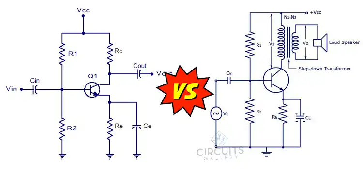
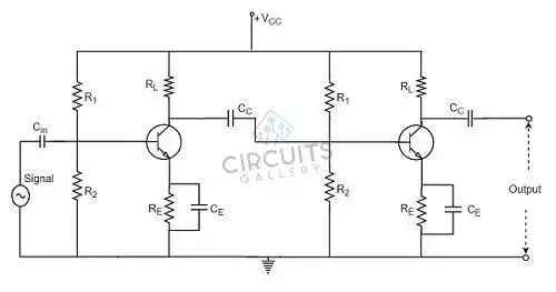
Resistor-capacitor coupling (RC) is a common method for linking stages in amplification circuits, using a resistor and capacitor combination to connect outputs, allowing AC components to pass through, and blocking DC components.
Working Principle
The base of a transistor in an RC coupled amplifier receives the input AC signal through a coupling capacitor. This capacitor ensures that only the AC component of the signal is sent by blocking the input’s DC bias. A second coupling capacitor is used to link the output of the first stage to the next stage. The resistor in this step acts as the necessary load to maintain the needed biasing while allowing the AC signal to flow through.
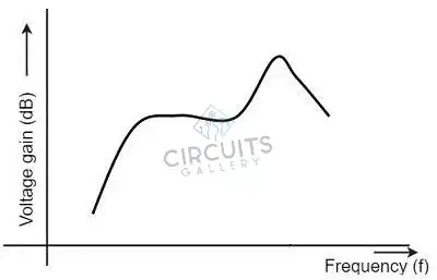
Frequency Response of RC Coupled Amplifier
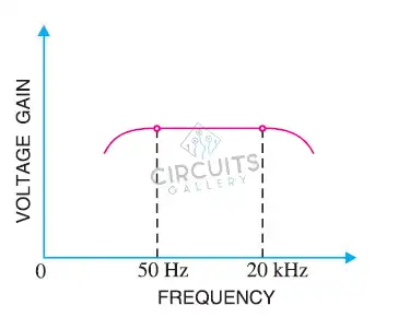
A graph that depicts the connection between voltage gain and frequency function is called a frequency response curve. The graph below depicts the frequency response of an amplifier that is RC linked. It is clear from the following graph that the voltage gain is constant for the frequency range between 50Hz and 20 KHz, but that the frequency rolls off or declines for frequencies below 50Hz and above 20 KHz.
We know that,
XC = 1/2πfc
It denotes that the relationship between the capacitive reactance and frequency is inverse.
Transformer Coupling
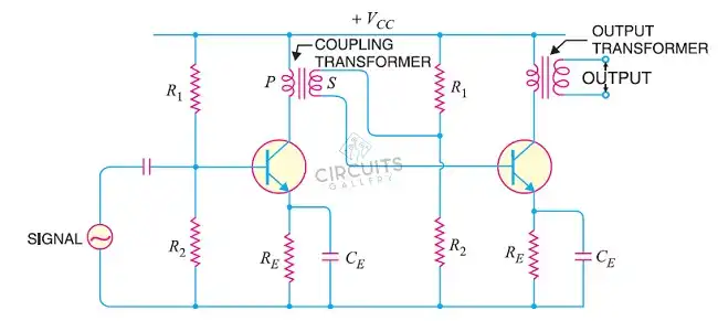
As the name implies, transformer coupling couples signals between several stages of amplification circuits using transformers. To effectively transmit signals, this method is frequently applied in audio and RF (radio frequency) amplifiers.
Working Principle
The base section of a transistor receives an alternating current signal, amplifies it, and the amplified signal is observed at the collector section connected to the primary transformer. The transformer performs coupling, utilizing the principle of varying impedance.
This results in the voltage from the primary winding being transferred to the secondary winding, based on the number of turns in the transformer. The transformer-coupled amplifier circuit is primarily used for power amplification, demonstrating its basic working principle.
Frequency Response of Transformer Coupled Amplifier
A transformer-coupled amplifier has a limited frequency response, with constant gain in the output voltage. The main reactance decreases at low frequencies, reducing gain. The capacitance between winding turns acts as a bypass condenser at high frequencies, lowering the output voltage and causing frequency distortion.
This results in disproportional amplification of audio signals.
Difference between RC Coupling and Transformer Coupling
Now that we are fully informed about these two couplings, including all of their benefits and drawbacks, we can create a table highlighting their main distinctions.
| Aspects | RC Coupling | Transformer Coupling |
| Principle | Uses capacitors and resistors for coupling | Uses a transformer for coupling |
| Frequency Response | Limited frequency response due to RC time constant | Broader frequency response |
| Amplification | Lower voltage gain | Higher voltage gain |
| Efficiency | Less efficient due to power loss in resistors | More efficient due to transformer properties |
| Isolation | Limited electrical isolation | Provides electrical isolation |
| Impedance Matching | Poor impedance matching | Better impedance matching |
| DC Blocking | Requires capacitors for DC blocking | Automatic blocks DC |
| Size and Complexity | Requires fewer components, simpler circuitry | Requires a transformer, relatively more complex |
| Applications | Audio amplifiers, simple circuits | Audio amplifiers, signal isolation, impedance matching |
| Cost | Generally low cost | Potentially higher cost due to transformer |
Transformer coupling is superior to RC coupling, as can be seen. Applications needing more voltage gain, better impedance matching, and electrical isolation are best served by transformer coupling. It is useful for maintaining signal quality across a range of frequencies since it has a wider frequency response and efficient energy transfer.
Galvanic isolation is also provided through transformer coupling, eliminating ground loops and noise interference. Its greater performance makes it the go-to option for the best signal transmission and quality, despite the fact that it can need a more complicated circuit and be more expensive.
Frequently Asked Questions and Answers – FAQs
What is the difference between direct coupling and transformer coupling?
Direct coupling and transformer coupling are electronic circuit stages connected for smooth signal transmission but can cause issues like DC voltage offset and distortion. Transformer coupling offers advantages like galvanic isolation and impedance matching, making it suitable for audio amplification and signal transfer.
Are there hybrid coupling methods that combine both RC and transformer coupling?
While less frequent, certain circuit designs may combine the two coupling techniques to make use of each technique’s benefits in particular signal processing applications.
Can transformer coupling be used for both AC and DC signal transfer?
It is true that transformer coupling may transmit both AC and DC signals, making it useful in a variety of circuit applications.
To Conclude
RC and transformer coupling are essential methods for transferring signals between amplification stages. RC is simpler and cost-effective, best for lower-frequency applications, while the transformer offers superior performance across frequencies. The choice depends on application requirements, frequency range, signal quality, size constraints, and budget considerations.
Subscribe to our newsletter
& plug into
the world of circuits