What Is the Range of 4-Bit Adder? | Maximum Output of a 4-Bit Adder
In decimal format, a 4-bit adder can operate between 0 and 15.
An important part of digital circuits and computer systems is the 4-bit adder. It can add two 4-bit binary values to produce a 4-bit sum output and also produces a carry-out output if the sum is greater than 4 bits. The range of a 4-bit adder is determined by the numeric representation (usually binary).
The highest number that can be represented by 4 bits is 15 (1111 in binary) and the lowest number is 0 (0000 in binary). Therefore, the operating range of a 4-bit adder is 0 to 15 in decimal format and 0000 to 1111 in binary format.
Designing and evaluating digital systems requires an understanding of a 4-bit adder’s range since it establishes the maximum number of arithmetic operations that may be carried out.
What is a 4-Bit Adder?
A combinatorial logic circuit called 4-bit adder binary adds two 4-bit binary values. Carry propagation uses flip-flops and logic gates (AND, OR, XOR gates, etc.). These parts work together to process binary numbers and produce the sum (S) and carry (Cout) outputs in the adder circuit.
Binary addition is performed by adding matching bits of the input numbers from right to left. The result, whether 1 or 0, is directly affected by the sum. However, if the sum is 2 or greater, a carry is made to the next bit position.
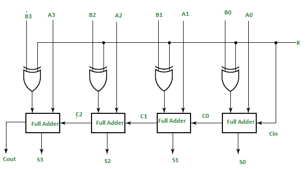
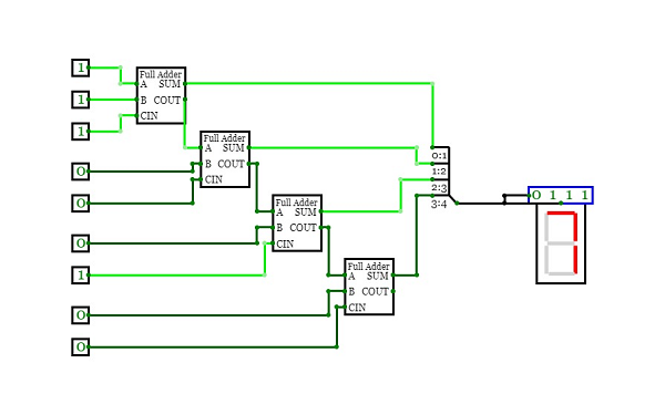
Image 1: A 4-Bit Adder
The 4-bit adder finds applications in arithmetic logic units (ALUs), processors, and microcontrollers. Its comprehension forms the basis for binary arithmetic and enables the exploration of complex digital systems.
What is the Maximum Range of a 4-Bit Adder?
A 4-bit adder operating on binary values represented by 4 bits provides 16 range possibilities. This corresponds to the decimal range 0-15. These numbers represent the minimum and maximum totals that a 4-bit adder can add.
Each bit position of the two 4-bit binary numbers contributes to the total when added. If all bits are set to 1, the maximum sum is 1111 in binary or 15 in decimal. In contrast, minimum sum occurs when all bits are set to 0 (0000 in binary, 0 in decimal).
For example, combining the binary numbers 0101 (decimal 5) and 0011 (decimal 3) using a 4-bit adder yields 10000 (decimal 8). Overflow occurs here because the sum exceeds the 4-bit threshold and the most significant bit is truncated.
Understanding the device domain is important to ensure correct arithmetic operations within the constraints of a 4-bit adder. This allows correct circuit sizing and allows the designer to anticipate future overflow or underflow situations.
Frequently Asked Questions
How does a 4-bit adder handle overflow?
Overflow occurs when the output of a 4-bit adder exceeds the number of bits it can store. In this situation, the most significant bits (MSB) of the sum can be truncated and information can be lost.
What happens when there is an underflow in a 4-bit adder?
4-bit adder underflows when the result of the subtraction is less than the minimum representable value. Underflow conditions must be properly handled to ensure correct computation under these circumstances.
Can a 4-bit adder be cascaded or combined to handle larger numbers?
Yes, many 4-bit adders can be cascaded or combined to handle larger numbers. This method uses many stages of 4-bit adders to add n-bit binary values.
Conclusion
The operating range of the 4-bit adder is 0 to 15 in decimal format and 0000 to 1111 in binary format. The set of all possible output values for adding two 4-bit binary numbers is represented by this range. Designers can anticipate future overflow or underflow conditions and ensure proper circuit sizing with area considerations.
Subscribe to our newsletter
& plug into
the world of circuits