When Soldering a Lug Onto a Copper Wire | Answered
Soldering a lug onto a copper wire is a common electrical task that is used to create a strong and reliable connection between two wires. Lugs are typically used to connect wires to terminals, circuit boards, or other components.
Soldering a lug onto a copper wire is a common electrical and electronics soldering task that requires precision and proper technique to ensure a reliable and secure connection. Here are some additional tips and steps for this process.
Gathering the Essentials
Before embarking on this task, ensure you have the following materials:
1. Soldering Iron
A soldering iron is the primary tool for melting solder and creating a strong bond between the wire and the lug.
2. Solder
Solder, a metal alloy, is used to join the wire and the lug, ensuring a robust electrical connection.
3. Rosin Flux
Rosin flux acts as a cleaning agent, removing oxides and impurities from the surfaces, and enhancing solder flow and adhesion.
4. Lug
A lug is a metal terminal that provides a larger surface area for soldering, ensuring a stronger connection and preventing wire damage.
5. Wire Strippers
Wire strippers are essential for removing the insulation from the end of the copper wire, exposing the bare metal for soldering.
6. Wire Brush
A wire brush effectively removes dirt, oxidation, and debris from the wire and lug, ensuring a clean surface for optimal solder adhesion.
7. Heat Shrink Tubing (Optional)
Heat shrink tubing provides insulation and protection to the soldered joint, preventing damage from moisture, corrosion, and external factors.
Preparing the Wire and Lug
To prepare the wire and lug, perform the following steps:
Cleanse and Deoxidize
Use a wire brush to thoroughly clean the copper wire and the lug, removing any impurities that could hinder solder flow and bonding.
Apply Flux
Apply a small amount of rosin flux to both the end of the stripped copper wire and the inner surface of the lug. Flux facilitates solder flow and promotes a strong connection.
Tinning the Wire and Lug
For tinning the wire and lug perform the following steps:
Tinning the Wire
Heat the end of the stripped copper wire with the soldering iron and touch it to the solder, creating a thin coating. This process is known as tinning.
Tinning the Lug
Repeat the tinning process with the lug, ensuring the inner surface is evenly coated with solder.
Soldering the Wire to the Lug
To solder the wire to the lug, perform the steps below:
Heat the Lug
Heat the lug with the soldering iron until it reaches the solder’s melting point. The lug should be hot enough to melt the solder but not so hot as to damage the wire insulation.
Insert the Wire
Insert the tinned end of the copper wire into the tinned lug, ensuring it reaches the bottom of the lug.
Apply Solder
Touch the solder to the joint between the wire and the lug. The solder will flow into the joint, creating a strong bond.
Allow Cooling
Allow the solder to cool completely before moving the wire or lug.
Inspect the Joint
Once the solder has cooled, inspect the joint to ensure its strength and integrity. Check for gaps or voids that may compromise the connection.
Heat Shrink Tubing Application (Optional)
To apply heat shrink to the tube, perform the steps below:
Cut the Tubing
Cut a piece of heat-shrink tubing slightly longer than the soldered joint.
Slide the Tubing
Slide the heat shrink tubing over the soldered joint, ensuring it covers the entire joint.
Shrink the Tubing
Using a heat gun or hair dryer, shrink the tubing to fit the joint tightly, providing protection and insulation.
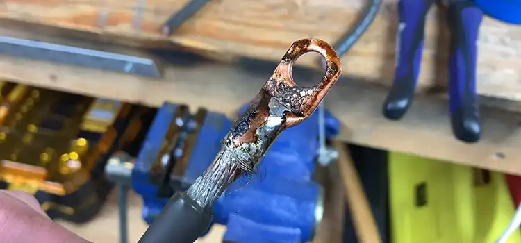
Following is the image of how a soldered lug and copper wire look like:

Figure 1: Soldered lug and copper wire
Frequently Asked Questions
What is a lug in the context of soldering?
A lug is a small metal connector or terminal that is attached to the end of a copper wire to facilitate secure electrical connections.
Why would I need to solder a lug onto a copper wire?
Soldering a lug onto a copper wire ensures a strong and reliable electrical connection, which is essential in various applications, such as electronics and electrical wiring.
What tools and materials do I need for soldering a lug onto a copper wire?
You’ll typically need a soldering iron, solder, flux, heat shrink tubing, and a lug suitable for the wire size.
How do I prepare the copper wire for soldering?
Strip the wire’s insulation, clean the exposed copper with sandpaper or a wire brush, and apply flux to the area you’ll be soldering to ensure a clean, oxidation-free surface.
What type of solder should I use for this task?
Use rosin-core solder with an appropriate diameter for the wire size, typically 60/40 or 63/37 tin-lead solder.
Conclusion
Soldering a lug onto a copper wire is a crucial skill in electrical work, enabling secure and reliable connections between wires. By following these steps and using the appropriate tools and materials, you can effectively join wires and ensure the integrity of your electrical circuits.
Subscribe to our newsletter
& plug into
the world of circuits