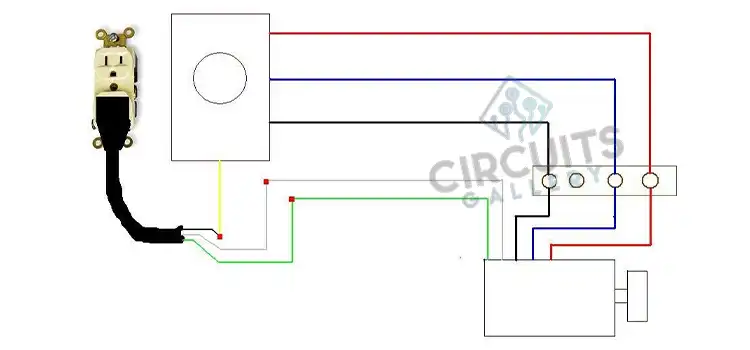
3 Wire Brushless Motor Wiring Diagram (Complete Guideline)
Three wires are essentially present in a three-wire brushless motor for control and power purposes. These motors may be used for a variety of everyday applications, including cooling fans for computers, RC cars, and drones. A brushless motor has three…